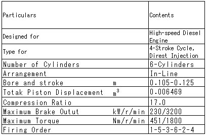
Table 1 Main Specifications of Test Engine
丂
Then, the inertia moment of damper inertia ring Id (= 0.330x10⁻²kgm2) can easily be calculated on the assumption that the damper inertia ratio R(= Id/Ie) is equal to 0.3 [25]*, [26]*. The clearance 兟 of the standard viscous damper is determined from the BICERA's empirical formula [27]* shown in the following.
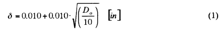
The clearance is determined to be approximately 0.0197 in = 0.50 mm by substituting D0 (=241.0 mm) = 9.49 in into equation (1). Then, the inside diameter of the casing becomes 242.0 mm. The dimension and the shape of the standard viscous damper shown in Fig. 1 were decided by considering those of the dampers widely adopted in the high speed diesel engines until the present.
丂
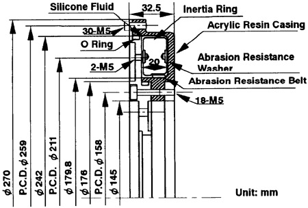
Fig. 1 Shape and Dimensions of Viscous-Friction Damper
丂
Table 2 Dimensions of Damper Inertia Ring
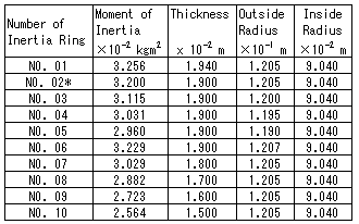
*Designed Standard Viscous Damper
丂
3.2 Geometries of Various Dampers.
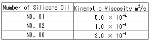
As shown in Tables 2 and 3, the dimensions of the inertia rings and the viscosities of the silicone oils, respectively, are diversely varied in this experiment, in order to investigate the dynamic characteristics of the viscous dampers. The number of the inertia ring of the standard viscous damper is No.2.
丂
Table 3 Kinematics Viscosity of Silicone Fluid
丂
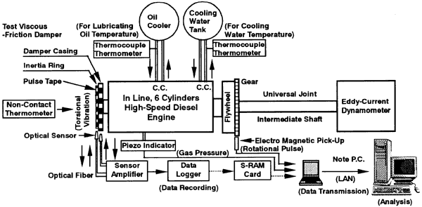
Fig. 2 Schematic Diagram of Measuring System of Torsional Vibration Waveforms at Tow Points
丂
丂
丂
BACK丂丂丂CONTENTS丂丂丂NEXT
丂