Inlet air enters the compressor system via a radial intake, designed to maintain uniform circumferential velocity at entry to the gas generator. The compression process is accomplished through two independently driven compressors, the Low Pressure (LP) and High Pressure (HP). Both compressors employ six stages and have commonality with their aero RB211-535 origin. The compression process is split 30:70 between the LP and HP compressors. Air delivered from the LP compressors is cooled by an on-engine heat exchanger using a closed loop flow of freshwater/glycol (FW/GL). The FW/GL is itself cooled in a freshwater/seawater (FW/SW) off-engine intercooler. The cooler air exiting the intercooler requires less work from the HP compression system enabling an overall improvement in specific power and additionally provides a lower recuperator air side inlet temperature permitting maximum heat recovery in the recuperator. Intercooling alone is inherently less efficient because heat is lost from the cycle, however, the combination of the recuperator and the intercooler recovers the deficit and the overall engine efficiency is improved.
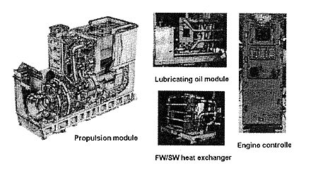
The on-engine intercooler comprises modular heat exchanger segments of a plate-fin configuration and made from 70/30 copper/nickel. The FW/SW off-engine intercooler uses a titanium plate frame heat exchanger and is separately mounted on its own baseplate along with pumps, valves and associated equipment as shown in Figure 3.

Figure 3 WR-21 Main System Components
The recuperator is used to recover heat from the exhaust and pre heat the HP compressor delivery air prior to combustion. The heated air (through recuperation) requires less temperature rise (and hence less fuel burn) within the combustion process to achieve the required turbine entry temperature.

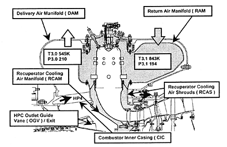
Figure 4 Combustion System
The combustion system, shown in Figure 4, consists of nine radially mounted combustors housed within an annular delivery air manifold (DAM). This manifold collects and delivers air via two ducts to the recuperator. Within the DAM is located a second annular manifold which collects and distributes the hotter air returning from the recuperator to the combustors.
The gas generator turbines share commonality with the aero RB211 parent with coating changes to maximise corrosion resistance.
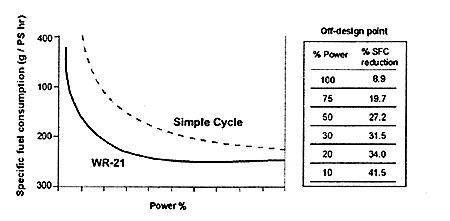
After passing through the gas generator turbines gas enters the power turbine. The power turbine blading (stages 2 to 5) incorporates three dimensional orthogonal blading design common with the latest Aero Trent parent. The first stage of the power turbine is unique to the WR-21 with the incorporation of a row of Variable Area Nozzles (VAN) that control flow area. The VAN is used to optimise the recuperator performance across the power range by controlling the power turbine capacity (and hence engine mass flow) which in turn maintains a high recuperator gas side inlet temperature. The VANS which are hydraulically operated are fully open at full power but progressively close with reducing power maintaining a nominally constant recuperator inlet temperature. This has the effect of retaining the efficiency across the whole power range by maximising recuperator heat recovery at part powers, giving the characteristic flat fuel consumption curve of the WR-21, shown in Figure 5.

Figure 5 WR-21 fuel savings versus simple cycle
The recuperator is mounted on the enclosure downstream of the exhaust collector. A plate-fin construction was selected as the optimum heat exchanger design solution providing high levels of effectiveness, compactness and robustness. The recuperator cores are manufactured in modules thereby enabling easy installation and removal. The ducts that direct air to and from the recuperator include valves to enable recuperator bypass to be accomplished. The bypass facility, if required, heats the cores to provide recuperator cleaning or alternatively to isolate the recuperator in the event of battle damage. . The engine system is contained within an acoustically and thermally lagged enclosure, Figure 6, which is sealed to prevent leakage of nuclear, biological or chemical contamination to the engine room.
BACK CONTENTS NEXT